
4 February 2026
Time Domain Reflectometry (TDR) – A Down-to-Earth Guide for RATMON Leak Detection
You ever notice how some technologies are quietly brilliant? They don’t shout about themselves, they just work. Time Domain Reflectometry – TDR for short – is one of those sneaky geniuses. It’s been around for decades, tucked away in labs and fault-testing gear, quietly tracing broken wires and soggy insulation. And yet, for something that sounds like it belongs in a physics exam, it’s surprisingly easy to grasp once you strip away the jargon.
TDR does what exactly?
Imagine shouting into a cave. You know that moment when you hear your voice bounce back, and you sort of estimate how deep the cave must be by how long the echo takes? That’s basically what a TDR does, except instead of sound, it sends a lightning-fast high frequency impulse (a fast-rising pulse rich in high-frequency content) down a wire and listens for echoes (technically known as reflections). Where the properties of the wire change, such as a broken connection, or a damp area, that pulse is reflected back.
Now here’s the trick: the TDR measures how long the echo takes to come home. That delay tells you how far down the wire the problem is. And depending on the shape of that reflection—whether it shoots up or dips down—you can guess what kind of problem it is.
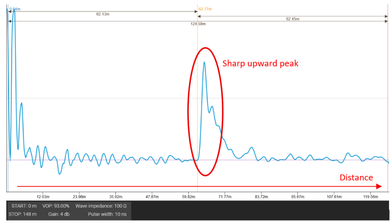
- A jump upwards on the graph? That’s a break in the wire or open end – the signal hit an obstacle on its way to the back of the cave.
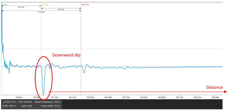
- A dip downwards? That’s usually a short or water bridge – something’s making the wires touch or leak current.
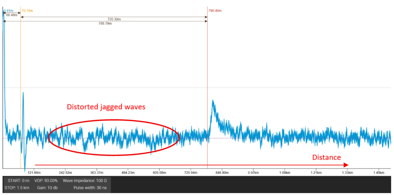
- A ripple? This is actually quite normal and could be because of crimped connections, interference or other minor changes in cable geometry. It could also be moisture creeping in or insulation starting to fail—like the first few raindrops on a dry window.
Impedance – what’s that word again?
Here’s where we need to discuss some technical terms. “Impedance” just means how hard it is for a pulse to travel through a cable. If the wire is uniform and dry, the impedance stays steady, and the TDR trace won’t show any major spikes or dips. But as soon as there’s a hiccup – a bad connection, a damp patch, a full-on break – the electrical environment (impedance) changes and causes you to get an echo (reflection).
In electrical terminology, impedance is a wire’s overall opposition to changing electrical signals. It combines the effects of resistance (how hard it is for DC current to flow), capacitance (conductors storing and releasing charge) and inductance (the magnetic fields that push back when current changes). This mix of resistance, capacitance and inductance determines how the high frequency impulse will behave when it’s sent by the TDR device.
Think of it like a car driving down a smooth road. Suddenly, there’s a pothole (or a puddle). The shock (an echo of sorts) travels back through the car to the driver (the device producing the TDR). Same idea with electricity.
- Open circuit (wire break): the signal runs out of road, causing lots of opposition to moving forward → the echo, or reflection goes up.
- Short circuit (wet bridge, wires touching): the signal skims over a puddle that has very little opposition → the echo, or reflection goes down.
- Moisture creeping in: subtle dips in the road, far apart. The echo is a broad, softer downward dip.
Measuring how far down the wire the trouble is
Here’s the clever bit: the TDR knows how fast signals travel through that particular sensor wire – called the velocity of propagation (VoP). Sometimes velocity factor will be mentioned (as either a decimal number or percentage) but VoP is the real-world, more accurate phrase, especially when the sensor wire’s environment (its moisture, temperature, insulation condition, etc) are used to tweak the actual value.
VoP is expressed as the percentage of the speed of light that a pulse can travel through that specific sensor wire, in those specific conditions. Not all sensor wires behave the same, and even the same type of sensor wire can shift slightly if it’s colder, warmer, wetter, or compressed. That’s why VoP is tailored – it belongs to the wire and its surroundings.
So, the TDR sends a high frequency impulse, waits for the reflection, and uses the VoP number to convert time into distance. The impulse has to travel out to the fault and back, which is why you divide by two, but the number you feed into the calculation – the VoP – is what keeps the measurement honest.
Calculation:
Distance ≈ (Velocity of Propagation × Round‑Trip Time) / 2
VoP for the MSC‑1 cable is well‑defined because it has stable insulation and geometry. Bare copper alarm wires, on the other hand, can wander a bit, especially if they’re sitting in damp insulation or running through junctions. So you often calibrate VoP by testing a known length.
The point is: VoP tells the TDR how quickly the pulse moves through the cable as it actually exists today, not just how it looked in a datasheet years ago. And that’s why it’s critical for getting the fault distance right.
Decoding those squiggly TDR lines
Let’s translate what the screen’s telling you. (If you’ve ever stared at one and thought, “What am I even looking at?”, you’re not alone.)
Healthy cable — boring but beautiful
+ |────────────────────────────────────────────── (flat = no faults)
0 |────────────────────────────────────────────── Distance →
– |
Open circuit (broken wire)
Short circuit (water or wires touching)
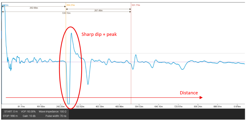
Substantial leak
Signal Interference
Wet pipe end
+ |
0 |────────────────────────────────────── Distance →
|
– |
Now, why does RATMON care about this?
Because RATMON uses this exact trick to keep tabs on its leak-detection wiring. Whether you’re using MSC‑1 insulated sensor wire or plain old bare copper alarm wires, TDR lets you pinpoint not just that there’s a leak—but where along the wire and therefore the pipe that it’s happening.
Here’s how it plays out in the real world:
- Cable break → Sharp upward jump on the TDR trace.
- Leak with water bridging the wire pair → Downward spike where it’s wet.
- Slow moisture ingress → A broad dip, fuzzy edges.
- Crushed or squashed insulation → Could go either way—depends how the impedance changes because of where the copper wire has been moved to (closer, or further away from the steel).
Set your TDR with the right VoP for your sensor cable (e.g MSC‑1’s spec sheet lists 85% for polyurethane foam), run a trace, and measure the blip. The graph tells you the distance. Then it’s a matter of finding that spot on your plan and checking the pipe there.
A field-friendly routine
- Start clean. Capture a baseline before the system is operational when everything’s dry and happy.
- When an alarm triggers, grab a new trace.
- Compare the two. See what’s new – an extra bump or dip usually means trouble.
- Translate the time to distance (a Ratmon TDR will do this automatically).
- Grab your tools and go check that section. Nine times out of ten, you’ll find your culprit.
Cables – same idea, different flavors
- MSC‑1 insulated sensor cable: designed for this job. Consistent performance, less chance of false readings from condensation. Stable VoP, which means your distance estimates are spot‑on.
- Bare copper/alarm wire: totally usable, just a bit noisier. You might get echoes from splices, clamps, or junctions. If possible, test a known length first to calibrate your VoP.
Handy quick-glance cheat sheet
| Pattern | Likely Cause | Action |
| Big upward peak | Cable break or open | Inspect for physical damage |
| Big downward dip | Leak, water bridge or short | Check for moisture ingress |
| Broad shallow sag | Slow leak or damp insulation | Monitor and plan inspection to take some DC resistance and galvanic measurements |
| Cluster of wiggles | Connections and joints | None, all good |
Pro tips from the field
- Always store your baseline trace – it’s your best friend later.
- There are known variables that can be used to calculate VoP based on the wire and its environment. Contact Ratmon for help with this.
- A big reflection near the start might mask others further down (it eats your signal) – fix the closest one first.
- Keep your test leads short.
Frequently Asked Questions
Will condensation trigger a false alarm?
Not usually. The MSC‑1 cable’s insulation shrugs off surface moisture. Real leaks make clearer, deeper reflections.
Can it spot more than one issue at once?
Yes – each event creates its own echo, like a hall of mirrors. Just start with the nearest strong one.
How accurate is it?
Pretty solid. With the right cable settings, you can locate a fault within a metre or two over long runs such as 500m or more.
A few parting thoughts
TDR might sound like an engineer’s party trick, but it’s quietly heroic in leak monitoring. It gives you eyes inside insulation you can’t peel open easily. In RATMON systems, that means faster fixes, fewer surprises, and no more digging blind.
And let’s be honest, who doesn’t love a bit of tech that can literally listen to a wire and tell you what’s going wrong around it? TDR turns invisible problems into visible squiggles – and if you know how to read them, those squiggles can save a whole lot of time, water, and money.
Recent News

27 February 2026
RISO – The Unsung Early-Warning Hero of RATMON Leak Monitoring
3 February 2026
Protecting Critical Infrastructure with RATMON’s Leak Detection Solutions for Data Centres and District Heating
2 January 2026
Understanding the Nordic Two-Wire Leak Detection System
7 November 2025
Reviving Alarm Systems in Legacy Buried Heat Networks